Thermodiagnostics in Power Engineering
It’s almost impossible to imagine life without electricity. Yet even though almost every aspect of the modern world depends upon it, it’s all-too-easy to forget how demanding it is to produce and supply electric power for daily consumption. After all, transmission and distribution networks are highly complex systems of interconnected energy sources, and they don’t run on their own. When failures occur within electricity networks, they can lead to blackouts, or worse – destructive fires. Advanced thermodiagnostic tools , like Thermodiagnostics in Power Engineering is, have an important role to play in the prevention of these disasters. One such tool combines cutting-edge thermal imaging systems with the UAV, or drone, to give advance warning of a potential problem.
A delicate system
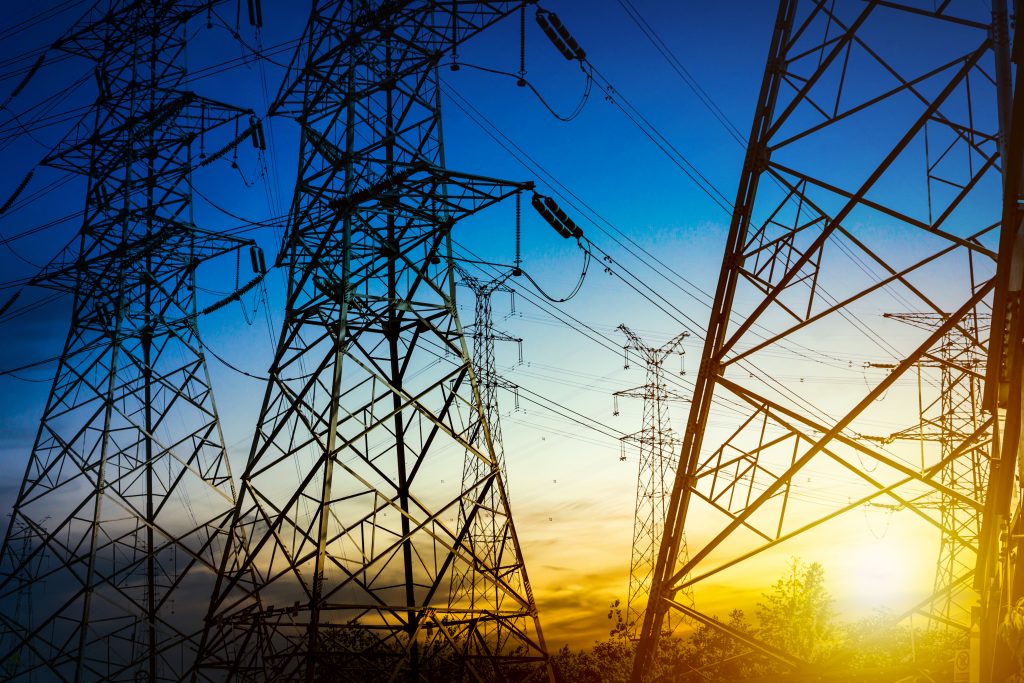
Electrical power stations produce AC currents with electric potentials of several thousands of volts. This energy must be transmitted over hundreds of miles to reach end-users, and it shouldn’t be surprising that this process requires several different components. Transformer stations, for example, connect transmission and distribution elements. They transform electric potential into very high voltages of 110 kV, 220 kV or 400 kV. Then, individual electrical power stations are connected to the distribution network by the overhead lines that end-users see crisscrossing the countryside.
Critical failure
Each element of this distribution network is at risk of a series of defects that can result in energy loss and/or a major security risk. Needless to say, an electricity supply breakdown that is caused by a distribution network failure does not only affect the electricity supplier’s profit – it has a direct impact on numerous consumers. Since everyone needs electricity, these consumers include companies as well as vital health facilities. An electricity failure poses a direct threat to the lives of vulnerable consumers. Therefore, proper maintenance and monitoring of each of the elements of the distribution network is absolutely critical.
Transition resistance
One of the most frequent failures in the distribution network is caused by components overheating under the stress of transition resistance. Transition resistance occurs in imperfect (damaged, outdated or unprofessionally installed) electric joints. Due to the increase in series resistance, there are energy losses in the form of what is known as heat loss. As time passes, the problem grows, until the temperature of the damaged joint can spark a fire. Even worse, the combination of fire and high voltage can lead to what is known as a ‘flashover’ – an electrical arc that endangers everything in its path.
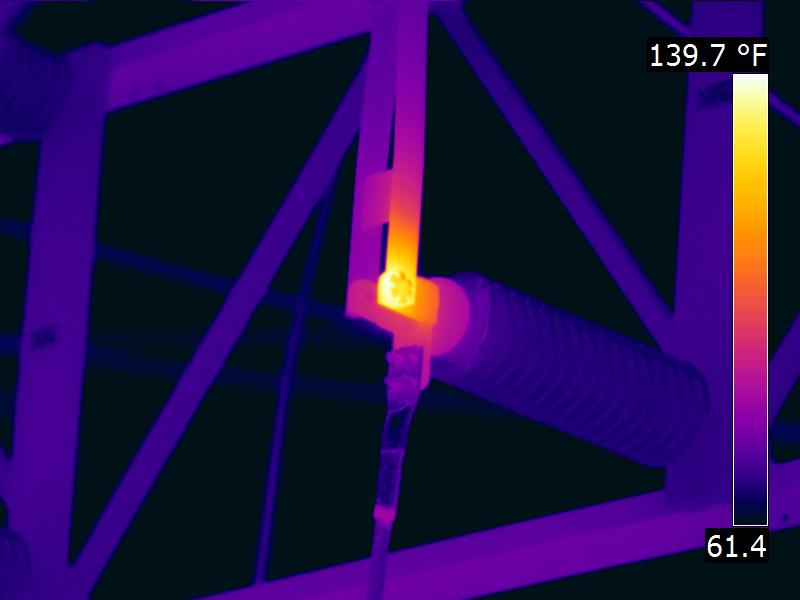
Thermographed joint
on a high voltage distribution line
Thermography is the technical field concerned with the contact-free determination of the allocation of a temperature field on the surface of a given body. Special measuring devices known as thermal cameras are used for this purpose. A thermo-camera can measure the surface temperature of an object from a few meters away (so long as that object has a sufficiently high emissivity value).
When mechanical inspectors use a thermal camera, they can unearth problems that cannot be seen on a traditional camera, even though they can lead to serious problems in the near future. A major advantage of this method is that it facilitates the investigation of installations that are already in use at full or partial operational load. Thus, instead of requiring operational shut-down, thermal camera inspections can only be carried out during normal operations – a major boost to efficiency. In fact, full operational loads enhance the accuracy of the inspection.
Thermal camera inspections must be conducted at regular intervals because a problem can occur at any time. After all, age and climate are constant stressors on even the most sophisticated equipment.
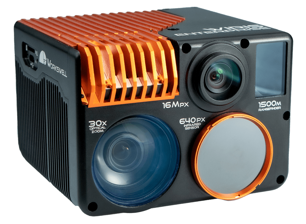
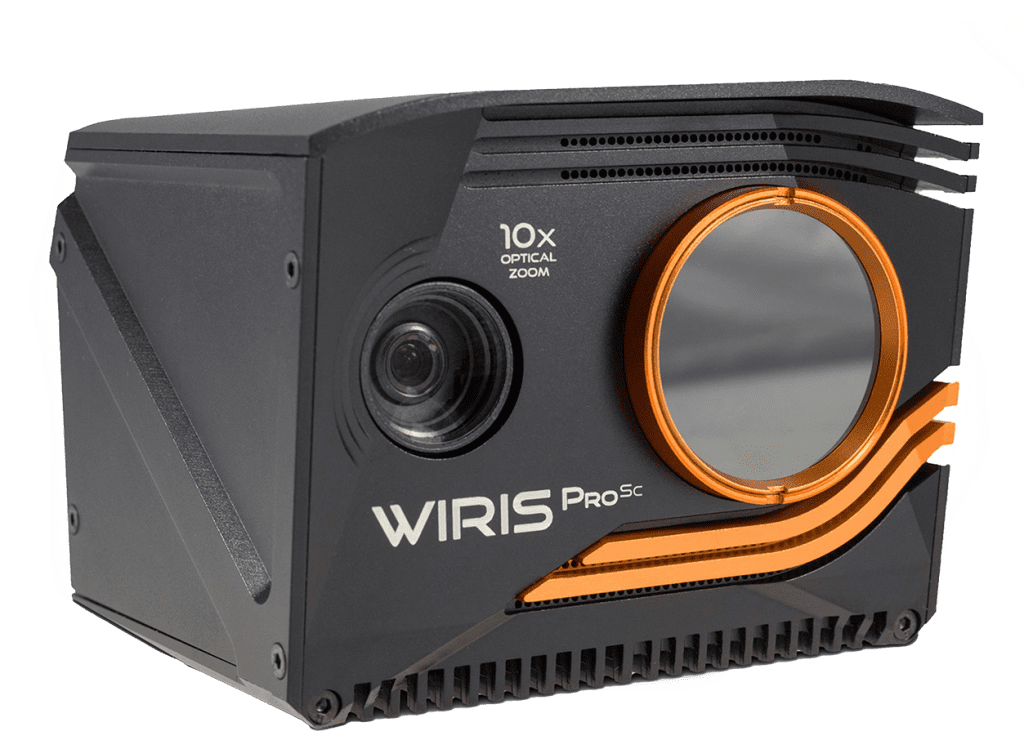
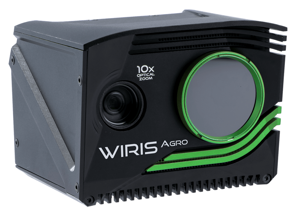
Aviation inspections using
the Workswell WIRIS system
So, maintenance is necessary – what can be done about equipment mounted at great heights? Many high-voltage fixtures are mounted in hard-to-access locations. Furthermore, in large transformer stations, the electrical system extends over an expansive area, making specific components very difficult to access. Aviation-based inspections have been used to enhance maintenance in these difficult cases for many years.
Combination of two systems
The thermal imaging system of the Workswell WIRIS thermal camera is designed with drones (UAVs) in mind. The set is light and mobile, and it can be fully manipulated using a standard RC controller. WIRIS combines two camera systems – a camera for the visible spectrum (for inspection of visible piping defects) and a thermal camera (for the detection of hidden defects). The servicing software enables the remote control of camera regimes, the recording of radiometric videos, and the production of static images in both the visible and infra-red spectra. The operator sees any objects under the drone in real time and can analyze records in order to identify damaged areas.
Moreover, unlike similar systems, Workswell’s WIRIS enables manual manipulation of the temperature range, e.g. in intervals of 15 °C to 25 °C. The temperature range can even be changed in-flight. In other words, the system can be quickly calibrated to address a changing situation without needing to land. This capability comes in handy when WIRIS monitors components that are susceptible to minor moisture defects, which can build up over time. In addition, the system can be equipped with a GPS sensor that stores the drone’s location while recording.
Locatization of problem
WIRIS measures the full scope of temperatures, both at the center of the temperature range, and at the local minimum and maximum. Minima and maxima are localized by blue (minimum) and red (maximum) crosses. This function can be used to navigate the drone because the system automatically shows where the largest potential problem is located. These aren’t the WIRIS’ only advantages – continuous ZOOM (up to 14x for the thermal camera and 16x for the color camera) provides exact localization of the problem, and facilitates precise control of NUC calibration.
Workswell’s WIRIS thermal camera is fully controlled by a traditional RC controller from which all system functions can be accessed. In addition to all functions, the monitor displays images from the thermal camera as well as the color camera. Information about the measured temperature (min/max and central spot) is available during the flight.
Calibration and detailed radiometric data are essential
All data obtained by WIRIS (both video and individual images) is fully radiometric, so the measured images can be evaluated in the comfort of an office. What’s more, the system enables ISO 18434-1 compliance – it produces a measurement report that looks clean, is easy-to-read, and provides insight into all potential issues. We care about quality, so we ensure that the Workswell WIRIS system is fully calibrated. During production, we check each camera’s precision, and a calibration sheet with the precision of the measurement system is included in every delivery. The system thus fulfills the requirements of the most well-recognized standard — ISO 18431-1. The emission and apparently reflected temperature values can be corrected at any time. Experts know that without this option, they cannot truly trust their data.
Summary
Thermography is a well-established control technique for a wide range of electrical installations. It was first used in 1965, and has since become the most widespread commercial use of thermography.
Aviation thermography has been the gold standard in this field from the very beginning. The Workswell WIRIS represents a complete aviation inspection system that fulfills the requirements of the ISO 18434-1 standard across measurements (calibration, radiometric data, correction of emissivity, and the other parameters of measurement). During the flight, inspectors monitor live images from both cameras, and a record of the whole flight is produced for further analysis. Inaccessible terrain and large substation areas present no problems for drones with cameras, as the whole system can be comfortably controlled from a safe distance. This provides a significant improvement over ground-based inspections with manual thermal cameras, to say nothing of standard visual inspections.